Blog Archives
LM358 microphone amplifier

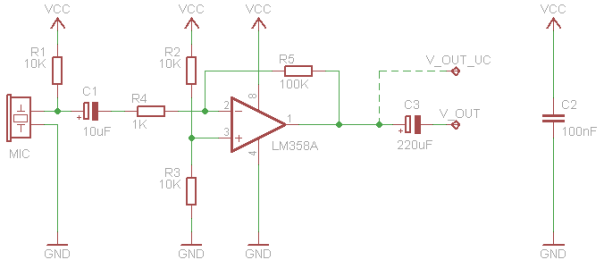
After the unconvincing performance of the LM386 mic amp, another design is put to the test. This time, based around a LM358 operational amplifier.
Read the rest of this entry
LM386 microphone amplifier

In this schematic, a LM386-based audio amplifier takes its input from an electret microphone.
LM386 audio amplifier
If you are building a sound sensor for your microcontroller, chances are you settle on a LM386-based microphone amplifier. It’s cheap, readily available and doesn’t require too many external parts.
A nice feature of the LM386 is that it can drive a small speaker. This allows for an easy design and test of the amplifier in isolation, using a portable music player and a desktop speaker. Once the amplifier works fine, adding a microphone to complete the sound sensor should be easy.
Schematics
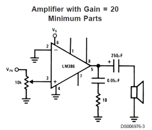
The LM386 datasheet provides a couple of schematics and the following description:
The LM386 is a power amplifier designed for use in low voltage consumer applications. The gain is internally set to 20 to keep external part count low, but the addition of an external resistor and capacitor between pins 1 and 8 will increase the gain to any value from 20 to 200.
The inputs are ground referenced while the output automatically biases to one-half the supply voltage. The quiescent power drain is only 24 milliwatts when operating from a 6 volt supply, making the LM386 ideal for battery operation.
What the datasheet fails to mention is that this chip may be a little tricky to work with – it turns out quite sensitive to noise and interferences.
LM386 pinout
Let’s have a look at the pinout and see what is the role of each part in the schematic above.
 Pins 1 and 8 control gain. When not connected (NC), the amplifier gain is 20. Adding a 10uF capacitor between them gives a gain of 200. Intermediate values are also possible, as described in the datasheet.
Pins 2 is the negative input – GND in our case.
Pin 3 is the positive input – i.e. the actual signal to be amplified. There is a 10K potentiometer before it, which adjusts the input signal level, acting as a volume control.
Pins 4 (GND) and 6 (Vs) provide the supply voltage for the amplification. For this setup a 4x AA NiMh battery pack is used, which provides ~5V.
Pin 5 is the output. It is biased to 1/2 of the supply voltage Vs. In simple terms, this means that the signal there has two components: An AC component, which is the amplified input signal, plus a DC component of 1/2 Vs = 2.5V. This biased voltage cannot be fed directly to a speaker, but is exactly what we need for a μC sound sensor. The 250uF electrolytic capacitor filters out the DC component and the remaining AC goes to the speaker.
The 0.05uF capacitor and 10 ohm resistor pair from pin 5 to ground turns out to be called a “Boucherot cell” or “Zobel Network” and is used to prevent high frequency oscillations.
Pin 7 is just named bypass, but the datasheet does not provide any further detail on it or its usage.
On a breadboard
Following the schematic above, all the components and wiring are placed on a breadboard.
The music player is connected using a “breakout” 3.5mm female jack. The input signal is over the yellow wire. Volume control is already present in the player, so the 10K potentiometer is left out. This brings the number of required parts to just three!
 Ground connections are in black; Positive voltage is in red; Output is over the green signal path.
A minor detail – I didn’t have a 0.05uF (i.e. 50nF) capacitor at hand, so two 100nF capacitors are used in series.
OK, everything is set, pressing “Play” and….
My first attempt with this was a disaster. There was nothing but crackling coming out of the speaker, with some faint resemblance of music in the background. Back to research.
Schematic, revised

v.2.0 of the schematic, drawn in EAGLE
One of the gray areas on the first schematic was the optional bypass capacitor on pin 7 – it’s shown on some of the other schematics in the datasheet, but has no value assigned to it. Google returned several results, the most useful being some forum thread:
A small electrolytic or tantalum cap of a few uF from pin 7 to ground will isolate the high gain input stage of the LM386 from power supply noise, hum, transients, etc.
 Another common way of dealing with power supply noise is adding a small (100nF) decoupling capacitor next to the IC power pins – C5. Depending on the exact wiring and on the power source, you may also need another one, larger in value (100uF) – C6.
In my experience, the presence of these capacitors turned out to be decisive, especially when working on a breadboard. If they turn out not to be sufficient, there are a couple of other approaches, in battling hums and interferences:
- Keep all components as close to the IC as possible
- Keep all signal lines as short as possible. Especially important for the input path, as a long wire there acts as an antenna
There are also some slight changes to the component values from the original schematic. C3 and C4 have the much more common values of 220uF and 47nF, respectively.
Again, pressing “Play” and… much, much better this time! For such a simple amplifier, built with basic-grade components, it sounds quite decently.
Parts list
| Part | Value | Description |
| C1 | 1~10uF | Bypass capacitor |
| C2 | 10uF | Gain 200x. Optional. |
| C3 | 220uF | Output coupling capacitor |
| C4 | 47nF | Boucherot cell |
| C5 | 100nF | Power supply decoupling |
| C6 | 100uF | Power supply decoupling |
| R1 | 10R | Boucherot cell |
| VR1 | 10K | Volume control. Optional |
Downloads
Links
- Jose Pino’s LM386 amp
- Little Gem and Ruby – more sophisticated designs, based on LM386